|

| Build-Your-Own |
Main Panel
| Dipole Woofer | Crossover/EQ
| Circuit Board |
| System Test | Design
Models | Prototypes | Active
Filters | Surround | FAQ |
Audibility of allpass crossover phase
distortion
On the Dipole Models page and
under FAQ19 I indicated my preference for a low order
crossover between woofer and midrange, because of its reduced phase distortion.
In the extreme this would argue for a 6 dB/oct 1st order acoustic crossover,
which is exceedingly difficult and costly to realize, because it places
stringent demands on linearity and frequency response of the drivers used.
I had convinced myself that the phase distortion of a LR4,
24 dB/oct midrange to tweeter crossover is not audible, Ref.17.
Those same tests showed that changes in the phase shift at the very low end of
the spectrum influenced the character of some test tones. Together with some
comparisons between earlier speaker designs, which seemed to favor a model with
12 dB/oct crossover over the same with 24 dB/oct, I concluded that the woofer to
midrange crossover should be of low order. In retrospect I think that it might
have been an increase of non-linear amplitude distortion in the midrange driver,
which gave the impression of better bass.
Following are test results and a setup that you can
readily duplicate, if you like to investigate for yourself the audibility of
phase distortion of typical crossovers that have allpass behavior. The acoustic
lowpass output from the woofer and the acoustic highpass output from the
midrange add to a flat amplitude response, but the phase of the summed output
changes non-linearly with frequency. This is allpass behavior and it distorts
the time domain waveform.
Ideally the waveform is transmitted undistorted as with a
1st order 100 Hz Butterworth crossover, when lowpass and highpass outputs are
added.
The 2nd order Linkwitz-Riley, 3rd order Butterworth and
1st order Butterworth crossovers form a 1st order allpass when the polarity of
the midrange is reversed. The waveform is distorted. The high frequency spectral
content forms a sharp spike of opposite polarity to the input, followed by the
low frequency content of same polarity as the input.
The 4th order L-R crossover forms a 2nd order allpass when
woofer and midrange outputs are added. Again, the waveform is distorted, though
differently from the previous case.
The spectrum of the waveform, that is applied to the 100
Hz crossover, is shown below. It has a 50 Hz fundamental and harmonics at odd
multiples thereof. Each spectral component is transmitted in the above
crossovers with correct amplitude, but their relative phase is changed,
particularly between the regions below and above the 100 Hz crossover frequency.
The waveforms of A, B and C above are quite different and
it would not be unreasonable to expect that they sound different. Yet, I have
not found a signal for which I can hear a difference. This seems to confirm
Ohm's acoustic law that we do not hear waveform distortion. At least it seems to
apply to the phase distortion generated by typical allpass crossovers.
Invitation to verify test results
The waveforms above were generated with an active circuit
that duplicates the phase behavior of the different crossovers, but has
perfectly flat (within +/-0.1 dB) frequency response. The circuit is readily
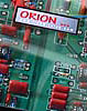
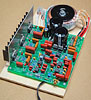
constructed using the WM1 printed circuit board.
While the board was not intended for this application it can be adapted by
adding a few wire connections and using jumpers instead of some
components. Capacitors may be placed where normally resistors would go and
resistors connected in parallel to as in the schematic with the WM1 board
component designations below. Only one trace needs to be cut. The circuit design is based on the
general
allpass configuration
Here is what I would like you to do:
- Build the circuit. Test it for flat frequency response
and equal gain in all three sections. Trim component values if necessary.
- For listening via a loudspeaker insert the circuit
ahead of your power amplifier. The speaker preferably has no crossover near
the 100 Hz region, or is a 2-way with good bass extension, to reduce the
possibility that its own phase distortion masks the contribution from the
test circuit, or that it pushes the total phase distortion above the
threshold of detection. A full-range Quad ESL might be a good speaker
candidate.
Quality headphones are probably even more accurate transducers, though
observations derived from them may nor translate directly to a loudspeaker
in a reverberant environment. Insert the circuit ahead of your
headphone amplifier.
Listen in mono.
- Listen to your selection of test signals or program
material and record any audible differences or lack thereof as you switch
between the sections. Record all test conditions so that others can
duplicate them, if possible. Note the playback level. Phase distortion may
increase the crest factor of the waveform (B above) and lead to non-linear
distortion in the speaker and/or the ear producing a change in sound
character.
- E-mail your observations to me. I will give a summary
of the various findings on this page.
I would really appreciate your participation in this
investigation. It could help to settle one more issue in knowing what is audible. I am
not trying to prove that all allpass crossovers sound the same, they do not in
practice, and there are good reasons for it. I merely want greater certainty whether phase distortion is a
contributor and, I think, so would you.
Thank you.
PS:
You might be interested in the mathematics and
consider pre-processed test signals instead of building the circuit. We are
dealing with three allpass transfer functions.
The reference to compare to:
F0(s) = 1
1st order allpass:
F1(s) = (s - 1) / (s + 1)
2nd order allpass:
F2(s) = (s2 - s 21/2 + 1) / (s2 + s 21/2
+ 1)
where s = s + j
w
First you would need to determine the impulse response for
F1 and F2, then translate it from 1 radian to 100 Hz, and convolve it with
the test signal time record. This can be done with MATLAB or similar software.
Test signals might be square-waves of different
frequencies, or other artificial signals, and speech, and music samples. The
results of the convolution are probably best stored on CD-R for comparative
listening tests. While this approach makes the analog circuit construction
unnecessary, it must be carefully executed not to introduce digital processing
artifacts and it limits the easy choice of test material.
Conclusion
The phase distortion of a 100 Hz acoustic crossover with
12 dB/oct or 24 dB/oct is not audible based upon the above tests.
This is my conclusion. No one has come forth with either confirming or
contradictory observations. I must assume that the whole question did not
generate much interest, or that readers had already an opinion that was not to
be tested. Maybe you just did not have the time to investigate.
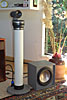
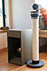
At 100 Hz a difference in acoustic path length of 1/8th
wavelength, causing 45 degrees of phase shift, corresponds to 43 cm (17 inch).
At 150 Hz crossover this decreases to 29 cm (11 inch) and makes the placement of
a separate woofer relative to the midrange that much more critical. I like to
keep offsets to less than 1/16th of a wavelength which makes it pretty much
mandatory at 150 Hz crossover frequency to integrate the woofer with the
midrange cabinet. This is not optimal for the woofer/room interaction which is
minimized when the woofer is placed near the side walls.
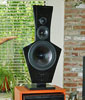
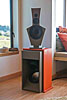
With the woofer separated from the midrange by some angle, a 12 dB/oct crossover
seems preferable to me, because the wider frequency overlap gives a more
distributed wave launch than a 24 dB/oct crossover, where the transition in
output from woofer to midrange cabinet is more abrupt.
| Build-Your-Own |
Main Panel
| Dipole Woofer | Crossover/EQ
| Circuit Board |
| System Test | Design
Models | Prototypes | Active
Filters | Surround | FAQ |
| 
